
After more than 35 years working with thermoelectric generators (TEGs), the most critical limitation I’ve encountered is heat flux management, not module efficiency! While thermoelectric modules are often rated for high power output, those ratings assume idealized boundary conditions, perfect system design, and heat flux densities that are rarely achievable in real-world systems.
Engineers always ask me what is the efficiency of the devices we sell, and I tell them it’s not about efficiency as it is about design, waste heat source, how much heat is directly available, proximity to the heat source, material and design restrictions!
Like photovoltaic panels, TEGs do not scale linearly with size. Increasing module count for the sake of filling up surface area is never the correct course of action. Unmanaged excessive heat flow within a confined footprint leads to excessive thermal resistance and heat flux bottlenecks. With current aluminum and copper heat-spreading materials, it becomes increasingly difficult to move sufficient thermal energy flux into and out of the thermoelectric modules to maintain an effective ΔT across the system. You can’t just place a TEG System on top of a stove. The steel is a HUGE resistor that slows the heat flow down to a crawl. Staving the system of what it needs most heat flow! Example: a 56 x 56 mm module requires ~400watts moving though the device! The is a huge amount of heat density through such a small surface area. A steel surface cannot even come close to moving this amount and density of heat! Result a 30-watt system only produces maybe BEST CASE 4 watts. Enough to move a small fan!
This conclusion is based on extensive empirical testing. Since 1996, I have designed, built, and tested approximately 80 complete TEG systems. all with various heat loads, sizes. Scaled small and large, and worked with another 300 to 500 clients, building their custom purpose-built systems. My earliest system used two solid aluminum plates (½″ thick × 5″ × 8″) with centered through-holes and liquid-based heating and cooling. Despite using six modules rated at 5 W each, the system produced only ~1 W total output under realistic operating conditions. The theoretical ΔT of 300°C/30°C was unattainable due to thermal coupling losses, liquid flow paths, interface resistance, and working fluid temperature limitation.
Over the next 16 years, I iterated through roughly 30 internal company designs. Some came close in demonstrated sufficient performance, and or cost efficiency to justify patent protection. Not until 2012 did we achieve a uric a moment.
The first IPOWERTOWER™ prototype utilized two 40 mm thermoelectric modules in series, operating at approximately 290-310°C (Heat SINK) on the hot side with a 600C flame and 80°C on the cold side. Initial output was ~3-4 W. The module count was limited by the ability of the cold side reservoir volume which was stagnant liquid in a column. the water volume was 1.2 liters of liquid. By modifying the thermal architecture—specifically by improving hot-side heat sink surface area and reducing overall thermal path length—the second-generation design achieved ~6 W with identical thermal inputs, even though the hot side was now 265-275°C. This showed how well my improvements reduced thermal bottlenecks!
Attempts to increase output by adding additional modules resulted in diminishing returns. Each added module increased thermal resistance and reduced average ΔT, yielding only ~1 W of incremental gain per module—insufficient to justify increased material and system costs.
The breakthrough came from recognizing that system-level thermal optimization matters more than module count. Example: (Balancing the hot side and cold side heat absorption with heat removal).
Once the design in that configuration had been optimized via passive cooling! The only way to increase performance using the identical heat source was to increase the volume of liquid via thermosiphon-driven convection, with a gravity feed reservoir tank above the unit with 15 x the volume of liquid. This allowed stable operation, extended DT’s and therefore more overall consistent power output over extended times without parasitic power losses, and increase sustained ΔT. When integrated with high-efficiency DC–DC conversion, designed specifically for the nominal loads, therefore electrical conversions where in the high 95 to 98% using an MVPT algorithm the system provided regulated 5 V USB output and 12 V battery charging.
Now when clients come to me and ask for more power than 10Watts, the answer is more IPOWERTOWERS™ in series or parallel. As long as the heat source area is large enough to accommodate more IPOWERTOWERS™ the more additional 10 watts units can be added!
“Critically, larger monolithic systems consistently underperformed. Optimal performance is achieved by deploying multiple identical units in series or parallel, distributing thermal load over a larger effective surface area while maintaining manageable heat flux per module”.
In thermoelectric power generation, distributed scaling outperforms centralized scaling. Bigger systems are not better—better thermal architecture is.
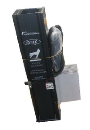
10 watts reservoir version
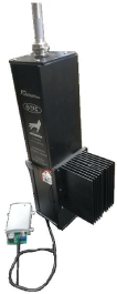
Thermo Syphon
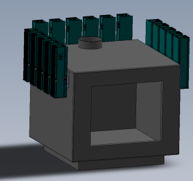
MODULAR. SCALED TO 180 watts
Effective design distributing heat flux over a
large area